Draw Rock Box
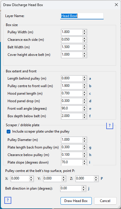
Right-click the Layers table on the Chute Faces tabsheet and choose Draw Rock Box... to add a rock box inside a discharge head box.
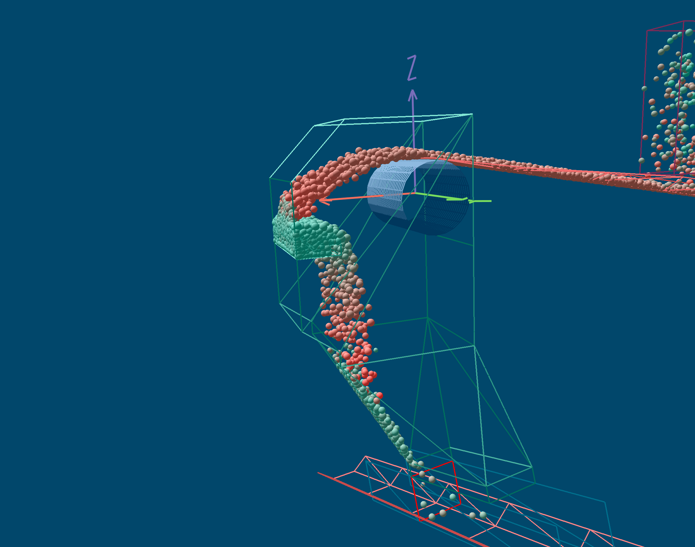
A rock box is used in place of an impact plate. It is a ledge fixed to the head box's front wall, in the path of the discharge from the pulley. Material builds up on the ledge into a heap, and from then on the stream lands on that heap of its own material rather than on steel – the heap cushions and absorbs the impact, and takes the wear that would otherwise fall on the plate.
What it draws
Ten faces, in a layer of their own:
- Plate – the flat ledge, fixed to the front wall and running back toward the pulley, across the head box's full inside width or a narrower width of your own, centred.
- Side Panel Left and Right – a triangular panel at each edge of the plate (at the side plates, for a full-width plate), from the front wall down to the plate.
- Side Wear Plate Left and Right – a narrow wear plate along each side panel's sloping edge, where the material running off the heap wears it most.
- Wear Bar (top, front, back and two ends) – a hardened square bar along the plate's open edge, which protects the edge the material slides over.
Dimensions
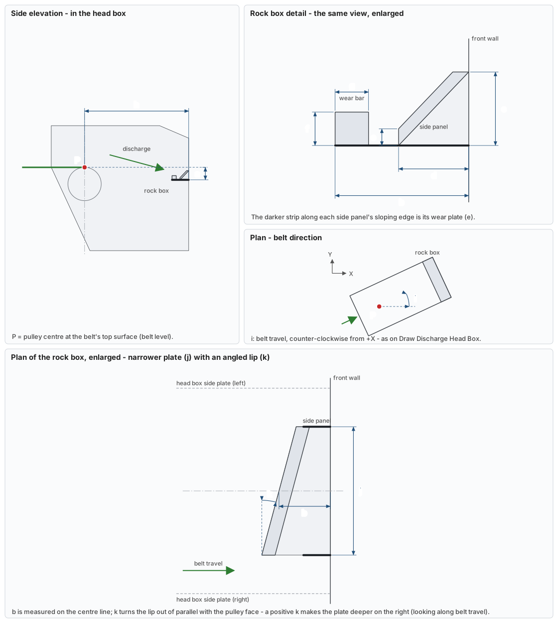
The small letters beside the input boxes match the dimensions on this drawing.
| Letter | Input | What it measures |
|---|---|---|
| a | Plate height below P | From P (belt level, at the top of the pulley) down to the plate's top surface. |
| b | Plate depth from front wall | From the front wall back toward the pulley, to the plate's open front edge. |
| c | Side panel height up wall | How far up the front wall each side panel reaches, above the plate. |
| d | Side panel length along plate | How far along the plate each side panel reaches, back from the front wall. |
| e | Side wear plate width | The wear plate along each side panel's sloping edge, measured straight up at the panel's open end. 0 for none. |
| f | Wear bar height | Usually 0.1 m. |
| g | Wear bar width | Usually 0.1 m. The bar sits on the plate with its outer face flush with the plate's front edge. |
| P | X, Y, Z (manual only) | The pulley centre, at the belt's top surface. |
| h | Pulley centre to front wall (manual only) | From the pulley centre line forward to the front wall. |
| i | Belt direction in plan (manual only) | The direction of belt travel, counter-clockwise from +X – as on Draw Discharge Head Box. |
| j | Plate width, centred | The plate's width across the box, centred on its centre line. Used when Full width of head box is unticked; never wider than the box. |
| k | Lip angle in plan | Turns the plate's open edge (the lip) and its wear bar out of parallel with the pulley face. 0 keeps it parallel. b stays measured on the centre line; a positive angle makes the plate deeper on the right (looking along belt travel) and shallower on the left. |
Angled lip – twisting the stream
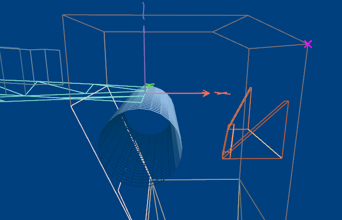
A rock box can do more than stop the stream: it can turn it. With the lip square to the belt, material spills off the wear bar evenly and falls straight down. Angle the lip (k) and the material leaves the heap across an edge that is no longer parallel to the pulley face, so it slides off with a twist – useful where the receiving belt runs at an angle to the feed belt. Demo 36 Copper Ore Transfer 72 degree angle onto loaded belt uses exactly this: its rock box plate is about 0.35 m deep on one side and 0.74 m on the other, a lip angle of roughly 18°, to help turn the stream through the 72° transfer.
The side panels and their wear plates are drawn on both sides as usual, each reaching no further along the plate than that side is deep. The wear bar follows the angled lip, keeping its full width square to its own length. The plate has to stay deep enough at its shallower side to leave room for the wear bar, and the dialog says so if it doesn't.
Full width or narrower
With Full width of head box ticked, the plate spans the box from side plate to side plate. Material landing on it then spreads right across the box and flows off the whole length of the wear bar – which changes how it arrives in, and flows down, the lower chute.
Untick it and give the plate its own Plate width (j) to keep the flow narrower. The plate is centred in the box, and its side panels and wear plates stand at the plate's own edges, so the heap – and the stream running off it – stays that wide. Run the calculation and look down on the head box to see how much the stream spreads.
Fitting it to the head box
Fit inside head box lists every head box in the drawing that was drawn with Draw Discharge Head Box. Pick one and the rock box is fitted to that box as it is now – against its front wall (following it if it leans), across the full width between its side plates, and measured down from its belt level – even if the box has since been moved or rotated as a layer.
A head box drawn by hand, or imported, can't be read this way, because its faces don't carry the names Draw Discharge Head Box gives them. Choose <enter manually> instead and enter the pulley centre P, the pulley centre to front wall distance, the inside width and the belt direction. A manually entered front wall is taken as vertical.
- If that space is too narrow, lumps falling off the rock box can bridge across it and block the chute. Check the clear gap below the rock box's open edge against your largest lumps – the Chute Design Guidelines rule of at least three times the maximum lump size is a sensible starting point.
- This matters most on slower belts. A slower belt throws a shorter trajectory, so the rock box has to sit closer to the pulley to catch it, and the gap left behind it gets smaller just as the material drops through it more slowly.
Like the other Draw tools, the dialog reopens with the values you last used, and drawing again with the same Layer Name asks whether to replace the existing rock box or add to it.